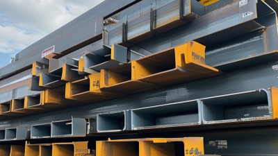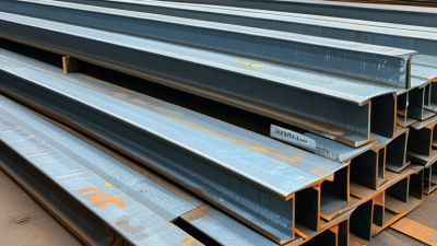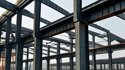
An I Beam is a structural steel section shaped with two horizontal flanges and a vertical web. That familiar profile does more than look sturdy. The flanges resist bending, while the web helps carry shear forces. Together, these parts make I Beams useful in many structures, from warehouse roofs and building frames to bridges and equipment platforms.
Engineering pioneer Theodore von Kármán wrote, “Scientists study the world as it is; engineers create the world that never has been.” His words offer a useful lens for understanding the I Beam: its shape is a practical response to the forces a structure must carry. Yet no single beam suits every job. Span, expected loads, support conditions, connections, and exposure to moisture or fire all affect the choice. A beam that looks oversized may still be poorly supported. Details matter.
This guide explains common I Beam uses and the factors that influence selection. It also looks at how engineers consider beam size, steel grade, deflection, and lateral bracing. For example, a long beam beneath a roof may need different checks than a short beam supporting a mezzanine. The examples are simplified, not design instructions; real projects should be assessed by qualified structural professionals using applicable standards. Steel is strong, but assumptions can be weak. One point deserves reflection: familiar shapes can encourage quick decisions, even when the surrounding structure changes the whole calculation.
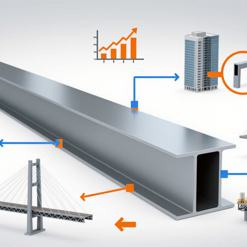
An I-beam is a structural beam whose cross-section resembles the letter I. It has two horizontal flanges joined by a thinner vertical web. The flanges sit at the top and bottom, where they help resist bending. The web connects them and carries much of the shear force between those edges. That shape uses material efficiently.
Picture a loaded beam spanning a room: its middle tends to bend downward, while its upper and lower parts experience different forces. Putting more material in the flanges helps the beam resist that bending without making the whole section solid. The web keeps the flanges apart and helps the section hold its form. Orientation matters; turning the beam on its side changes how well it resists bending in that direction. Small details count.
I-beams are commonly used in building frames, floors, bridges, and industrial structures, but the shape alone does not tell you whether a beam is suitable. Span, load, steel grade, connections, and support conditions all affect performance. It is easy to describe an I-beam as strong and lightweight, yet that shorthand can hide important limits. Useful, but not magic. A qualified structural professional selects and checks the beam for its actual job.

I-beams support loads by carrying bending forces across a span and transferring them to columns, walls, or girders. Their wide flanges resist much of the bending, while the vertical web carries shear between them. Together, these parts provide stiffness without requiring a solid block of steel. That sounds simple. It isn’t always.
The American Institute of Steel Construction’s ANSI/AISC 360-22 specification lists ASTM A992 wide-flange steel with a minimum yield strength of 50 ksi (345 MPa). Its listed minimum tensile strength is 65 ksi (450 MPa). These are material properties, not the safe load for a particular beam. Actual capacity depends on span, beam size, bracing, connections, and how loads reach the supports.
For example, a floor beam may carry joists spaced along its length, then pass their weight to a column at each end. If the beam’s compression flange lacks adequate lateral restraint, it can buckle before the steel reaches its expected strength. Deflection matters, too: a beam can remain strong yet feel noticeably springy underfoot. It is tempting to judge a beam by its depth alone. That misses the load path, and even experienced teams must check assumptions against drawings and site conditions.
Bending stiffness of a representative W12×26 steel section by axis
I-beams are commonly used as beams and girders to carry floor and roof loads to columns or walls. Their shape places much of the material in the flanges, helping resist bending. This chart compares the section’s moments of inertia—not its allowable load capacity. For the same material and conditions, greater moment of inertia means greater bending stiffness about that axis.
In buildings, I-beams often carry floors, roofs, and long spans between columns. Their wide flanges help resist bending, while the thinner web transfers shear through the section. On a construction site, a steel beam may support a row of concrete floor panels or frame an open retail space without many interior posts. That extra room matters. It can make layouts easier to change later.
I-beams also appear in bridges, elevated roadways, and rail structures. They can support deck sections while transferring traffic loads to piers and abutments. In a warehouse, they may carry roof loads across broad work areas; in a bridge, several beams can work together beneath the deck. Connections, bracing, and corrosion protection all affect how well the structure performs. The beam alone does not do the job.
Not every span calls for an I-beam. Engineers consider the load, distance, support conditions, fire exposure, and local environment before choosing a section. A beam that looks substantial can still deflect too much if its size or supports are poorly matched. And a tidy drawing can miss awkward details on site. That is worth checking. Proper calculations and inspections help ensure the whole assembly—not just the steel member—meets its intended demands.
I-beams carry loads across bridges by directing forces through their flanges and central web. In a bridge, they may support a road deck between piers or form part of a larger truss. The top flange resists compression, while the bottom flange handles tension under bending. The web helps manage shear forces. Important details. Engineers also consider span, traffic weight, wind, and connections to bearings. A well-sized beam can still perform poorly if bracing or joints are inadequate. Weather matters, too: water trapped around connections can accelerate corrosion, so inspection access should be part of the design.
In machinery and industrial buildings, I-beams often serve as frames, supports, and lifting-system runways. A workshop crane may travel along beams fixed high above the floor, keeping heavy components clear of work areas. Machine bases and mezzanine platforms use beams to distribute concentrated loads into columns. Fit matters. Designers check deflection, vibration, buckling, and how loads enter each connection, rather than judging strength by appearance alone. A beam that seems oversized can still be vulnerable at a poorly detailed joint. And an I-beam is not automatically the best choice; unusual loads or tight spaces may call for another section. That trade-off deserves a careful look.
What Is an I Beam Used For?
Factors That Determine Which I-Beam to Use
An I-beam carries loads across floors, roofs, and openings while limiting bending. Choosing one starts with the load: a roof may carry snow, while a workshop floor may support machinery. The beam’s span and support arrangement matter too. A long beam between two supports behaves differently from one fixed at both ends. Small details change the answer.
Section size is not just overall height. Flange width and thickness, web thickness, and steel grade affect strength and stiffness. Deflection matters as much as strength; a beam can resist breaking yet still sag enough to crack finishes or make a floor feel springy. That is easy to overlook. A deeper section may help, but it can also complicate headroom and connections.
The setting and construction method narrow the choice further. Outdoor exposure may require corrosion protection, while lifting limits or tight access can constrain beam weight and length. Connections must transfer forces safely into columns or walls. For example, a beam spanning a garage opening needs checks for roof loads, deflection, bearing, and how its ends are attached. A catalog table is a useful starting point, not a design. I-beam selection can feel untidy, and rough estimates often miss a condition on site. Have a qualified structural professional verify the final size against actual loads and local requirements.
| Factor | What to Assess | How It Affects I-Beam Selection | Common Applications |
|---|---|---|---|
| Span and support conditions | Distance between supports, whether the beam is simply supported or continuous, and how its ends are connected. | Longer spans and different support conditions change bending moments, shear forces, and deflection. The beam must be checked for the actual structural arrangement. | Floor beams, roof beams, bridge girders, and transfer beams. |
| Loads and load pattern | Dead loads, live loads, equipment loads, wind or snow effects, and whether loads are distributed or concentrated. | Load magnitude, location, and applicable building-code combinations determine the required bending, shear, and connection capacity. | Building frames, industrial platforms, crane-support structures, and mezzanines. |
| Section properties | Section depth, flange width and thickness, web thickness, cross-sectional area, and published section properties. | These properties influence strength, stiffness, weight, and resistance to local buckling. Compare suitable sections using the applicable design standard. | Structural framing where a strong, efficient member is needed to carry loads across a span. |
| Deflection and vibration | Allowable movement under service loads, floor comfort requirements, and sensitivity of finishes or equipment. | A beam can meet strength requirements yet still be too flexible. Stiffness and vibration checks may govern the selection. | Long-span floors, office floors, roofs, and beams supporting sensitive machinery. |
| Lateral restraint and stability | Whether the compression flange is braced and the spacing and rigidity of lateral supports. | Insufficient restraint can lead to lateral-torsional buckling, reducing the beam’s usable bending resistance. | Roof and floor beams connected to properly designed bracing or deck systems. |
| Connections and bearing | Bolted or welded connections, end reactions, available bearing length, and the supporting column or wall. | Connection design and local web or flange behavior may require stiffeners, reinforcement, or a different section configuration. | Beam-to-column joints, beam-to-girder connections, and supported lintels. |
| Material and design standard | Steel grade, specified yield strength, toughness requirements, and the governing building or bridge code. | Material properties and design rules affect calculated capacity, detailing, inspection, and fabrication requirements. | Buildings, bridges, and industrial structures designed to applicable local standards. |
| Environment and durability | Exposure to moisture, salts, chemicals, temperature, and the required fire-resistance rating. | Corrosion protection, drainage, maintenance, and fire protection may be needed; these requirements can affect detailing and lifecycle cost. | Outdoor structures, marine or industrial sites, parking structures, and fire-rated building frames. |
| Practical constraints | Available section sizes, transport and lifting limits, clearance, fabrication access, and total installed cost. | A technically suitable section must also be available and practical to deliver, erect, connect, and maintain. | Renovations, restricted sites, prefabricated frames, and projects with limited headroom. |
Note: I-beams are commonly used as beams and girders to support floors, roofs, bridges, and industrial structures. Final section selection and connection design should be verified by a qualified structural engineer using project-specific loads, support conditions, and applicable codes.